
Description
Application and Importance of Monitoring Heating Systems
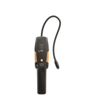
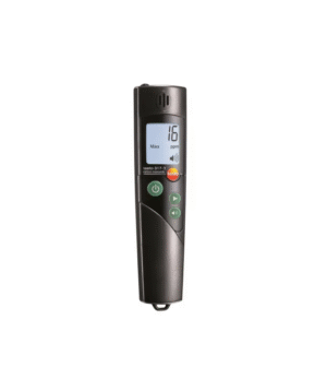
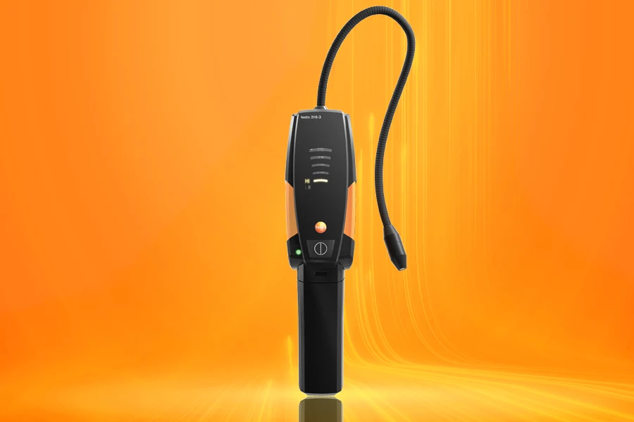
Measuring CO Concentration in the Ambient Air
Carbon monoxide (CO) is a colorless, odorless, and poisonous gas, which is a product of the incomplete combustion of fuels containing carbon (oil, gas, and solid fuels). When carbon monoxide enters the bloodstream through the lungs, it actively binds with hemoglobin, blocking the transfer of oxygen to tissue cells, resulting in death by asphyxiation. Thus, it is extremely important to monitor CO concentration at the hot point of flue gases, as well as in areas of potential threat to human life (in our case, in the locations of fuel-burning installations for hot water systems), and in other adjacent premises.
Measuring Draft in the Flue (Differential Pressure)
In fact, draft measurement is the measurement of differential pressure. Differential pressure arises between two sections due to a temperature difference, resulting in flow compensation. In the application area under consideration, the differential pressure value indicates the flue gas draft. During measurements, the pressure value between the ambient environment and the flue is displayed. Measurements are performed at the center of the flow.
In low-pressure systems, proper removal of flue gases through the chimney is mandatory due to sufficient differential pressure (flue gas draft).
If the draft values are too high, the average flue gas temperature increases, leading to heat loss with the flue gases. Consequently, the system’s operational efficiency is reduced. If the draft values are too low, a lack of oxygen during the combustion process causes an increase in CO concentration and soot number, which also leads to a reduction in the efficiency of the entire system.
Flue Gas Measurements for Burner Commissioning (CO, O
2
, and Temperature)
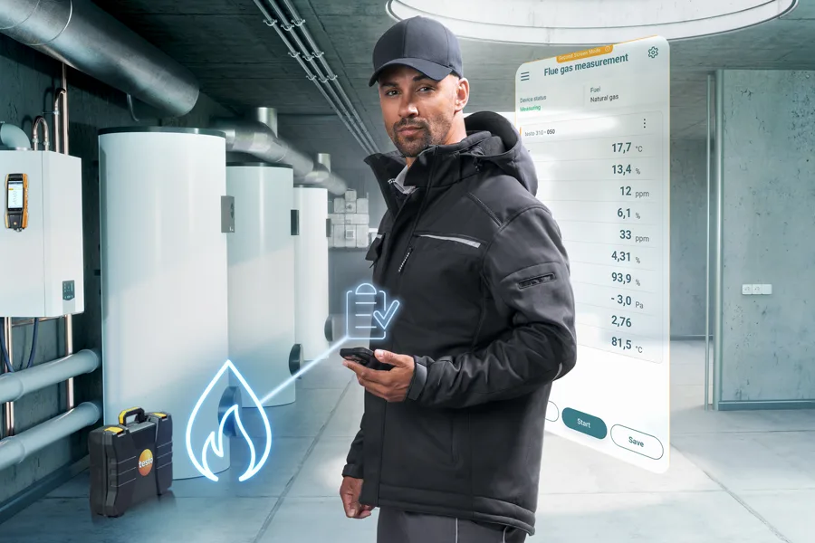
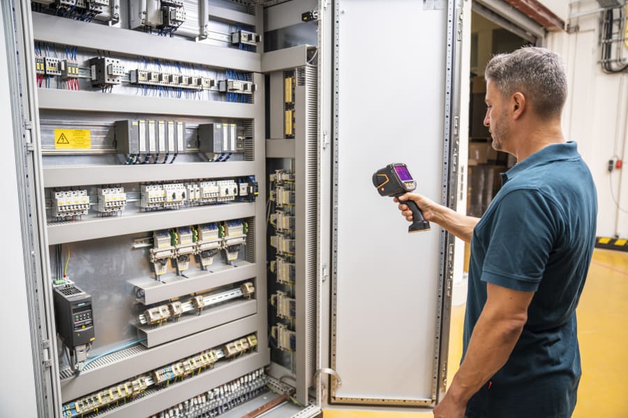
Flue gas parameter measurements for checking heating systems allow for the determination of the amount of pollutants emitted into the atmosphere with the flue gases (e.g., carbon monoxide – CO), and also to calculate heat losses with the flue gases. In some countries, flue gas measurement requirements are stipulated by law. The adoption of such laws pursues two main goals:
- The maximum possible reduction of pollutant emissions into the atmosphere;
- Effective use of energy.
Exceeding the established maximum permissible values of atmospheric pollutants is prohibited. Compliance of the measured values with the permissible limits is checked during normal operation (measurements are performed with appropriate instruments before each system startup). For measurements, the tip of the sampling probe is placed in the center of the flue, where the temperature and flue gas concentration are highest.
The measurement data are recorded by the flue gas analyzer and can then be transferred for printing or to a PC for further processing and analysis. Measurements are carried out by the heating system installer during commissioning, and then, if necessary, four weeks after commissioning by a chimney sweep engineer or a representative of the supervisory authority. Subsequently, regular measurements are carried out at set intervals by an authorized service engineer.
Pressure Measurements (Gas Pressure at the Nozzle, Gas Flow Pressure)
Basic measurements when setting up residential heating systems include checking the gas pressure, which in turn includes measuring the gas flow pressure and the static gas pressure. Measuring the gas flow pressure involves measuring the pressure in the supply pipe, while static pressure measurements determine the pressure distribution in the quiescent gas. If the gas flow pressure value of gas boilers slightly exceeds the range of 18 to 25 mbar, operation is not permissible. If operation is carried out despite the exceeded values, the burner’s functionality is impaired, and an explosion may occur during flame adjustment, leading to the failure of the burner, and thus the entire heating system.
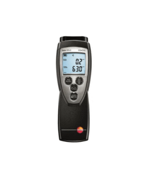
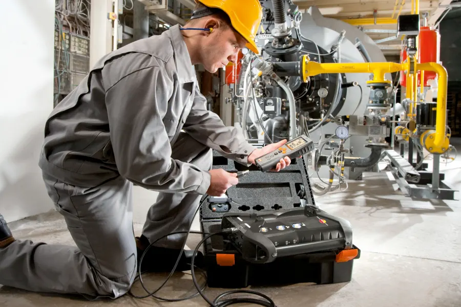
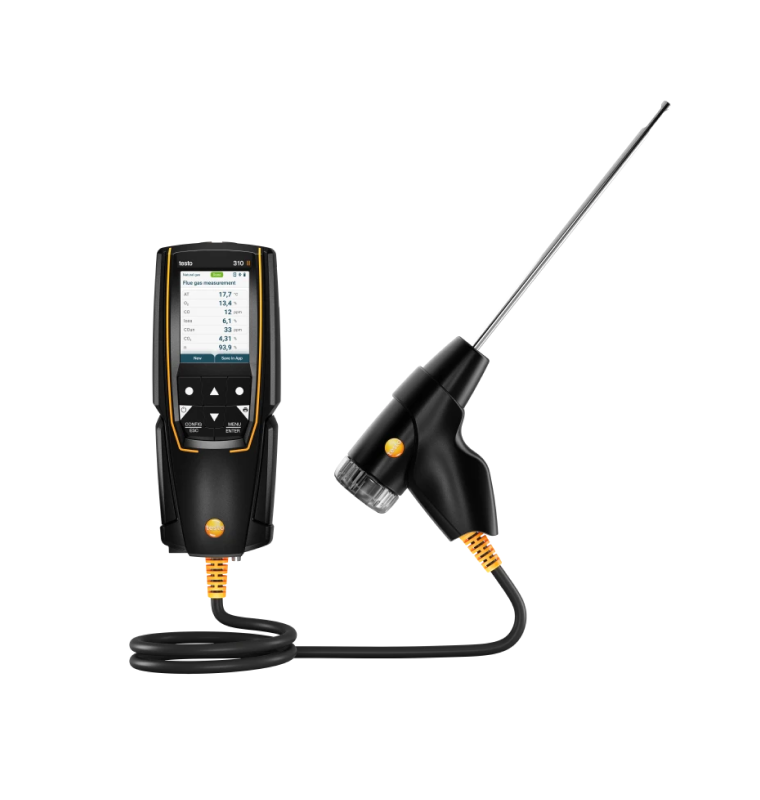
testo 310 Flue Gas Analyzer Kit
- testo 310 flue gas analyzer, with O
2
and CO measurement modules (0…4,000 ppm) - CO
2
concentration calculation - Draft, pressure measurement
- Sampling probe up to +400 °C, 180 mm long with fixed cone
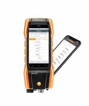
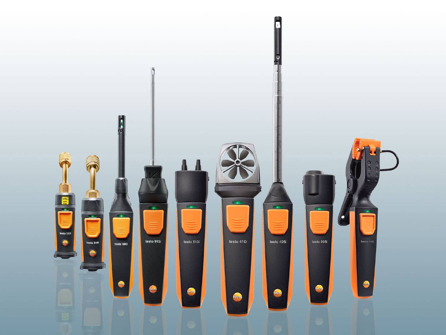
- testo 510i differential pressure manometer with smartphone operation
- Silicone hoses for pressure measurement (Ø 4 mm and 5 mm) with adapter
- Dust filters (5 pcs.)
- USB cable and factory calibration protocol
Flue Gas Analyzer (testo 310) and Smart Probe Manometer (testo 510i)
Flue Gas Analyzer (presumably testo 310)
Order No.: 0563 3106 10
Registered in the Register of the State System for Ensuring the Uniformity of Measurements of the Republic of Kazakhstan
28.03.2022 with No. KZ.02.01.01474-2022 type designation
Valid until 28.03.2027
General Technical Data
| Weight (with probe) | 690 g |
| Dimensions | 203 x 83 x 46 mm |
| Operating Temperature | -5 … +45 °C |
| Display Type | LCD |
| Display | 2-line backlit display |
| Power Supply | Rechargeable battery: 1500 mAh, power supply unit 5$\text{V}/1\text{A}$ |
| Storage Temperature | -20 … +50 °C |
Temperature Measurement (Type K Thermocouple, Ambient)
| Measurement Range | -20 … +100 °C |
| Accuracy | ±1 °C |
| Resolution | 0.1 °C |
| Response Time t 99 | < 50 s |
Temperature Measurement (Type J Thermocouple, Flue Gas)
| Measurement Range | 0 … +400 °C |
| Accuracy | ±1 °C (0 … +100 °C) ±1.5 % of meas. val. (> 100 °C) |
| Resolution | 0.1 °C |
| Response Time | < 50 s |
O
2
Measurement
| Measurement Range | 0 … 21 % vol. |
| Accuracy | ±0.2 % vol. |
| Resolution | 0.1 % vol. |
| Response Time t 90 | 30 s |
Differential Pressure Measurement (Flue Gas Draft)
| Measurement Range | -20 … +20 hPa |
| Accuracy | ±0.03 hPa (-3.00 … +3.00 hPa) ±1.5 % of meas. val. (in the remaining range) |
| Resolution | 0.01 hPa |
Calculated Parameters
| Efficiency (Eta) Determination | Range: 0 … 120 % / Resolution: 0.1 % |
| Heat Loss with Flue Gases Determination | Range: 0 … 99.9 % / Resolution: 0.1 % |
| CO 2 Calculation (via O 2 ) | Range: 0 … CO 2 max (Indication Range) / Accuracy: ±0.2 % vol. / Resolution: 0.1 % vol. / Response Time t 90 : < 40 s |
Pressure Measurement
| Measurement Range | -40 … +40 hPa |
| Accuracy | ±0.5 hPa |
| Resolution | 0.1 hPa |
CO Measurement (without H
2
-compensation)
| Measurement Range | 0 … 4,000 ppm |
| Accuracy | ±20 ppm (0 … 400 ppm) ±5 % of meas. val. (401 … 2,000 ppm) ±10 % of meas. val. (2,001 … 4,000 ppm) |
| Resolution | 1 ppm |
| Response Time t 90 | 60 s |
Ambient CO Measurement
| Measurement Range | 0 … 4,000 ppm |
| Accuracy | ±20 ppm (0 … 400 ppm) ±5 % of meas. val. (401 … 2,000 ppm) ±10 % of meas. val. (2,001 … 4,000 ppm) |
| Resolution | 1 ppm |
| Response Time | 60 s |